< News
Posted on 2020-02-24 | Tags: research-area-ears
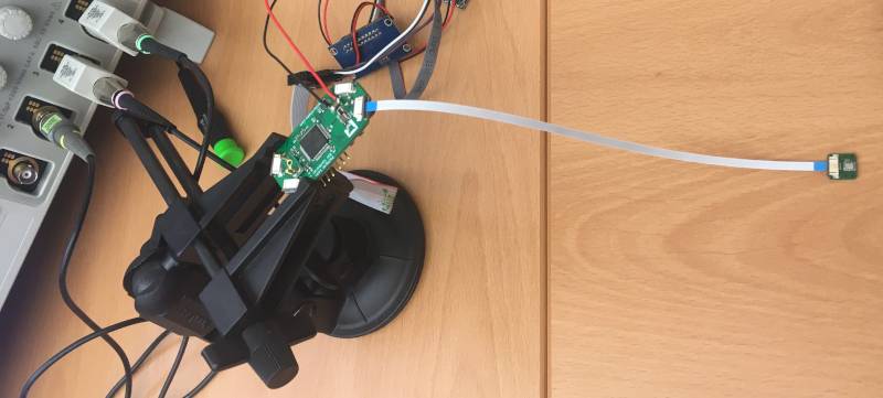
The current animatronic ear prototype has a central control board that processes audio from four microphones. These microphones send audio through the I²S protocol, which is a fairly simple digital serial protocol for audio.
The microcontroller on the control board sends two periodic signals to the microphone: the serial clock (3 MHz) and the word select signal (96 kHz). The microphone sends back audio samples on the serial data line, with one sample for each cycle of the serial clock.
The serial clock, word select, and serial data pins run on three adjacent traces on a 200 mm flat flexible cable. Because the traces are only 0.5 mm apart center-to-center and have no shielding, there is a risk of crosstalk interfering with the signals.
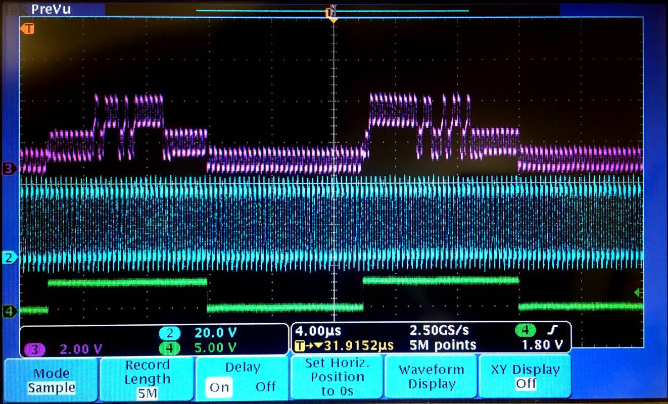
When I actually looked at the signals with an oscilloscope, I found that the crosstalk mostly overwhelmed the signals that the microphone was sending. In this example, the microphone drove the serial data line only when the word select was high. The serial clock and word select signals had peak voltages of 3 volts. Each of these two signals induced about one volt of crosstalk into the serial data. The actual signals from the microphone only caused about one volt of change in the signal. With a signal to noise ratio of about 0.5, there was no way that the microcontroller could receive the audio signals correctly.
I'm continuing to look for a more precise explanation for this problem. The microphone board was soldered imprecisely, which may be causing adjacent signals to get too close and couple too much. If that is not the cause of the problem, I may have to switch to another type of cable with better isolation between wires.